
Contrastick, the plan.
Contrastick, a bicopter with contra rotating motors is a successor for my flying stick design. This post is just about my plan to build one. The cad model and pictures, thoughts and ideas.
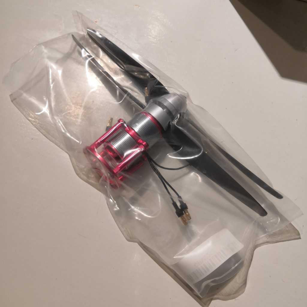
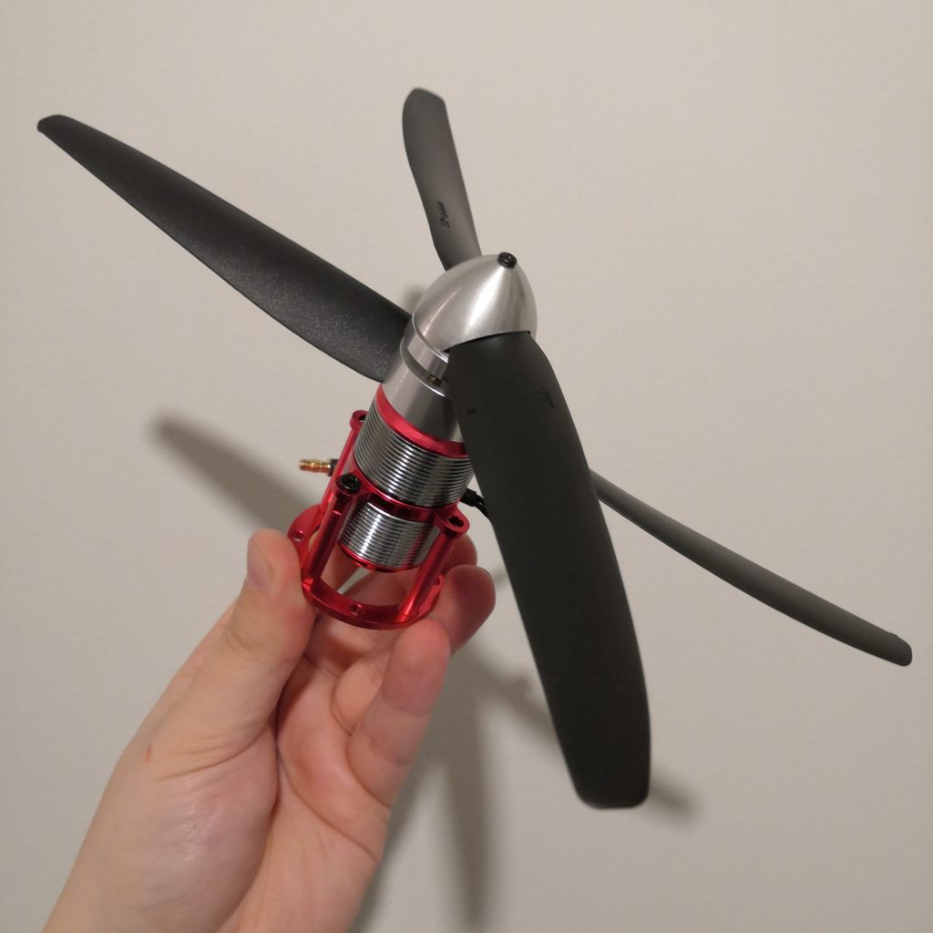
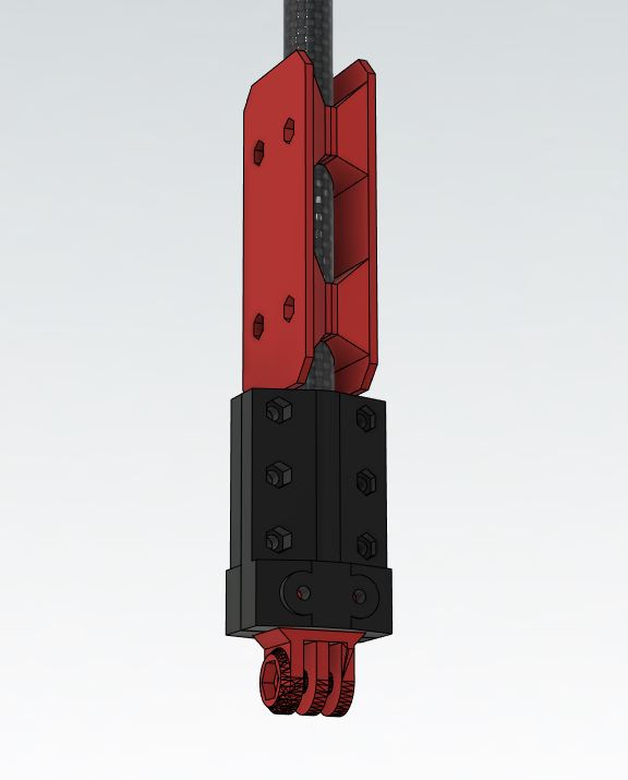
The motor I’m using with this build, two 2212 1400KV motors stacked together equipped with 9″ propellers. Motor came with a bracket I’m not going to use.
This motor on aliexpress.
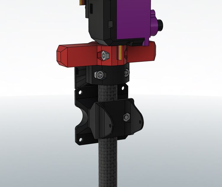
This here is my full cad model of the frame and build. The contra rotating motor at top and a GoPro style mount at the bottom. My idea there is to use this with a 360-camera. 360-cameras more or less always have a seam of some sort where it stitches the two videos together. The idea is that this whole flying thing would be cut out in that seam, thus making it almost invisible for the camera. I doubt it will be completely cut out of the picture but I expect most of it to be left out.
Another idea of mine was to attach some sort of 360 degrees spinning gimbal to the bottom, this way the gimbal would have unobstructed view to every direction. Gimbal like this would however add a lot of complexity and more moving parts to the build, as if it wasn’t complex enough already.
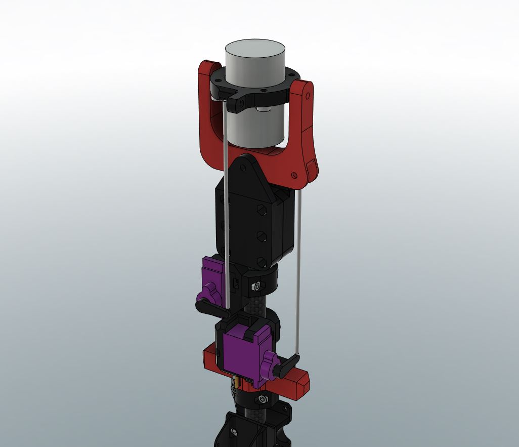
Motor mounting close-up.
A kind redditor notified me of a problem with this motor design however;
-“I believe when the red U shaped bracket tilts, the black bracket will forced to be tilted due to the linkage position. Your old version was fine since both axis intersects at the same height.”
He was right and I was a little ashamed for not noticing this myself. However I do believe that such problem can be fixed by mixing the movements of the two servos together so that the other servo cancels out the error created by tilting the mechanism.
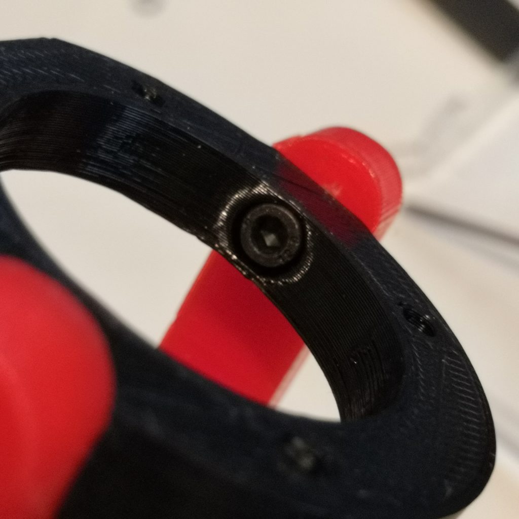

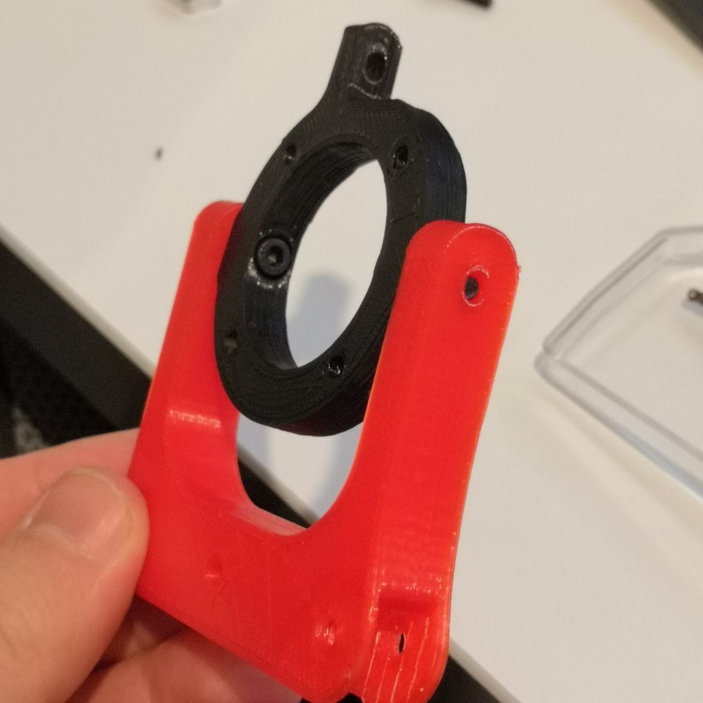
Motor mount. Screws mount the inner circle to the U-shaped bracket from inside out. There is also washers between the moving parts.
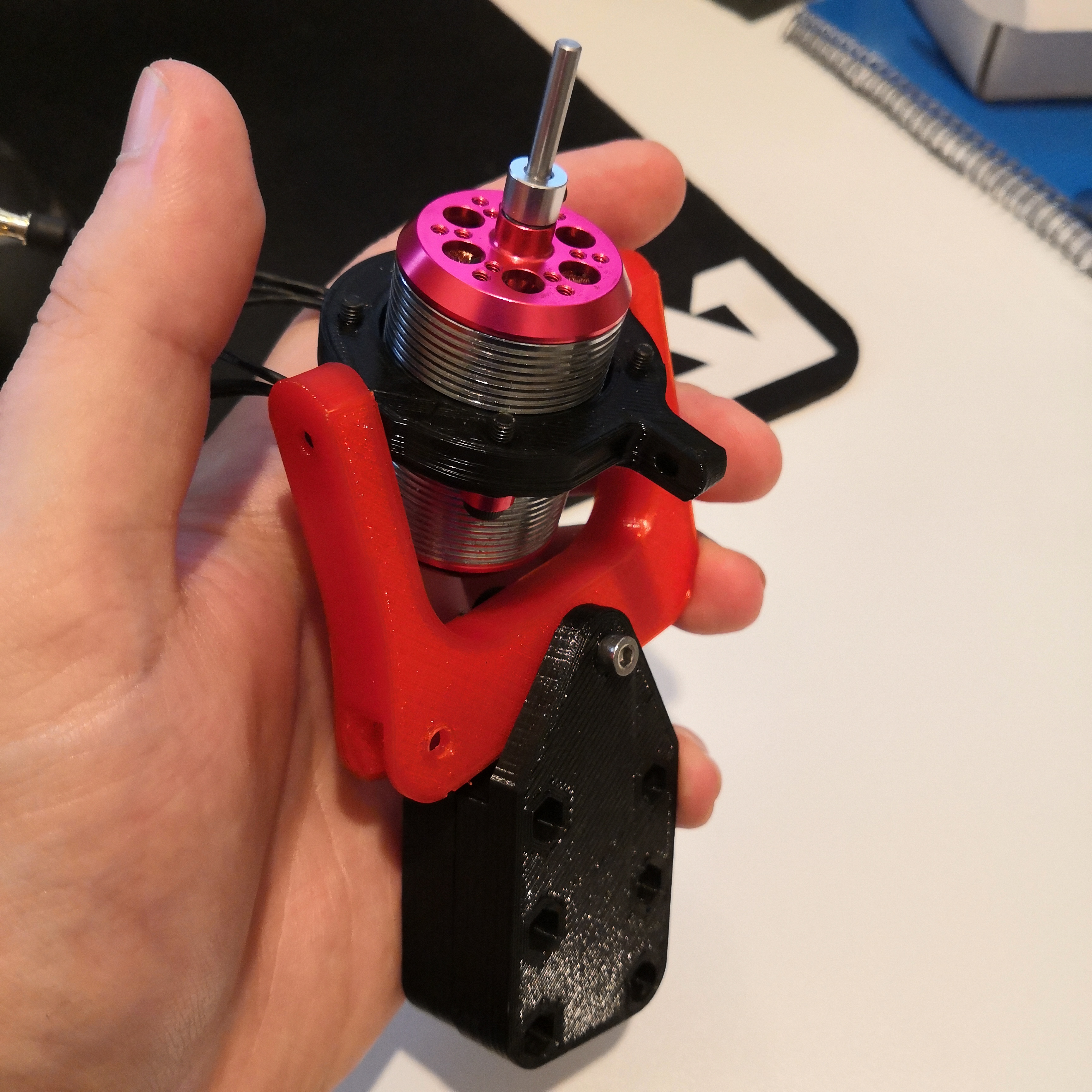
Very tight tolerances between the motor and the 3D-printed ring around it. (Note that the M3x12mm screws mounting the motor are a little too short for having a locknut on the other side.
I personally believe this design is better than on my older flying stick, mainly because in this version all of the thrust is in line with the “frame” and other components. There is no horizontal parts like in my old design, also joints from servos are a lot smarter now. To me this seems like a better way to approach system like this.
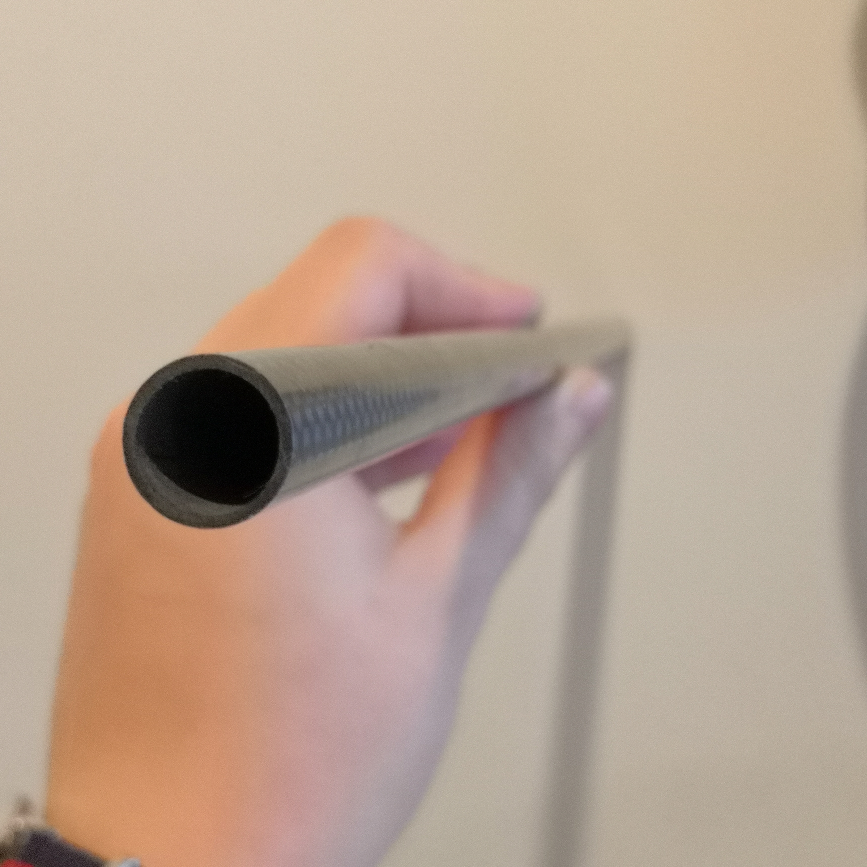
As a frame for this build I’m using the same kind of 12mm OD, 10mm ID carbon fiber tube I used with my previous stick too.
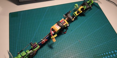
Middle part of the craft. Most of these parts here are same ones used in my original flying stick. Back then I made them so that they would be modular and re-usable in similar builds in future so yea, mission accomplished, good job past me.
I think I would like to also give this model a GPS like BN-880, that sould of course have a horizontal funky holder which would probably look silly.
That still needs planning.
Bottom part of the craft with that GoPro style mount. Dual battery plates also visible here.
Planned parts list for this thing:
- 2212 1400KV Contra-rotating motor
- MG90S 9g servos
- Matek F722-SE Flight Controller
- Spedix GS30A ESCs
- Caddx micro sized FPV camera
- HGLRC GTX226 VTX
- Crossfire Nano SE receiver with immortal-T antenna (for this I need to design a new mount)
- 2x 1300mAh 4S LiPos in parallel
This list may of course change in the future but I’m pretty sure it stays somewhat like this.
Comments are always welcome so if you have anything to say about this build and/or concept be sure to leave it below.
Great content! Super high-quality! Keep it up! 🙂
Is it possible to share the stl from this project. I have the all parts received so only print and fly 🙂
Hi!
Yes of course I can share the STL files and that’s great if someone else wants to build this too.
I have not actually built this yet so I can’t guarantee if all the parts really work together.
Here you can find the files here
https://www.thingiverse.com/thing:4262890
Happy building and please do post the build somewhere when it’s done 🙂
(Sorry for not noticing your first comment.)
Thank you, it is printing now. You will see the final.
Frank
“I believe when the red U shaped bracket tilts, the black bracket will forced to be tilted due to the linkage position. Your old version was fine since both axis intersects at the same height.”
The “problem” is not that both axis are not intersects at the same height, because that can be solved by servo travel. The problem is that the link on the motor ring should be at te front so no binding will occur.
But yes, inline will be a better option. I am making a drawing for that at the moment
You’re right about that. My planned solution for this was indeed to use mixers in INAV to compensate for the needed travel error.
I’m not 100% sure what you mean about binding though. There should not be binding happening because the pushrod can swivel around the servo arm too. Also using ball joint links as I did with my previous flying stick can help with these problems.
Anders
Contra stick is hovering, for some moments in the room. Now more tuning.
Frank
Hey, I am having trouble setting up my INAV programming for all the motors, could you provide some insight? Thanks 😀
Hi, I have (still) not built this myself so I don’t relly know if it’s a lot different than my other stick in that sense. Not knowing exactly what you meant I can only guess but one thing that comes to mind is that there are two different “pwm timer circuits” on your fc. make sure motors are on one and the servos are on another timer. If you use Matek fc this is well documented on their website.
If you meant how to set up mixers in INAV I can’t really help much with that, you just should figure it out for your specific setup 😛