
“A Flying Stick”
A flying stick, or a coaxial bi-copter, is what I decided to build once I saw the video by RCTESTFLIGHT. Even though he clearly didn’t put too much effort into the design the concept was cool and the idea was quite simple even if it might look complicated. I knew I could do much better job in creating one of these and make it more robust and durable while keeping it 90% 3D-printed.
It is pretty stable in flight but gets affected by wind a lot.
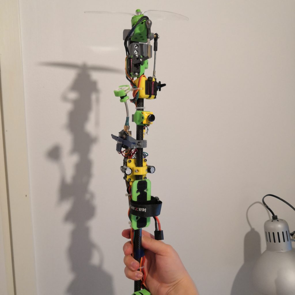
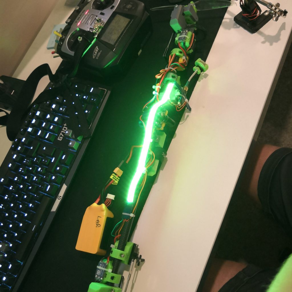
First of course, the finished product, an over engineered carbon fiber rod. I honestly kind of like how this looks. Reason for it to be printed in three different colors is that I first ran out of gray, then green and then had to finish it with yellow.
Assembly process
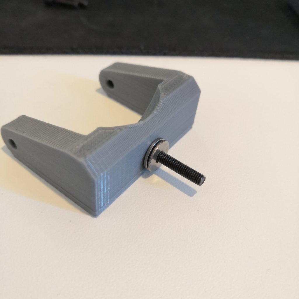
Begin by assembling the motor gimbals. M3x25mm screw on the first joint (in the picture that is 20mm, as you can see it’s a little too short) and M3x50-55mm on the second one. Also put ball joint things on and use washers between the joints to prevent prints from scrubbing against each other.
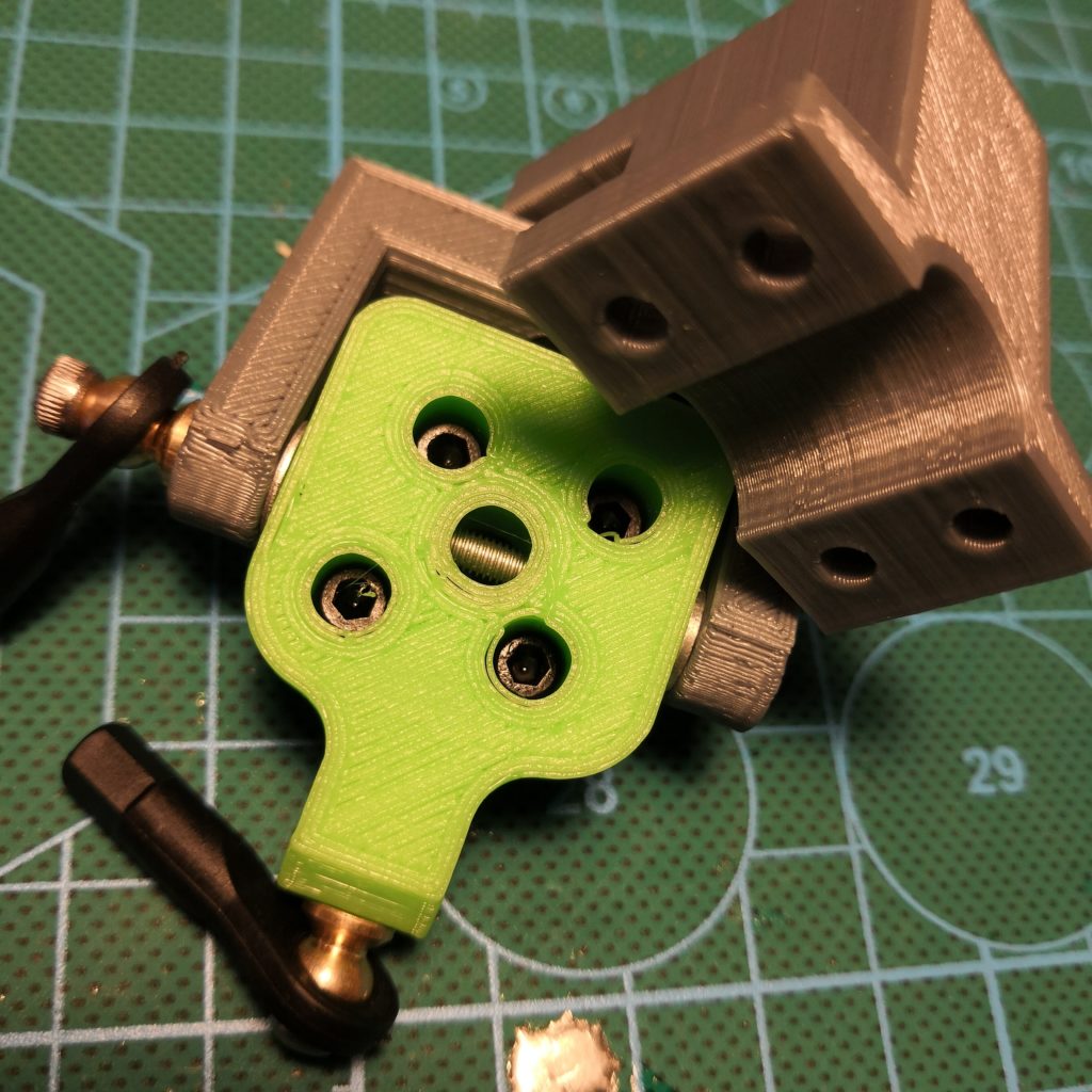

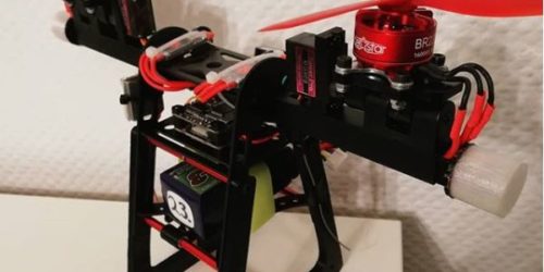
Next you put motor on that part. Should not be too complicated, just screw it in. With all four screws. The motors I chose were Racerstar BR2207 2200kv because I had these same motors, with lower kv tho, on my other bicopter and they perform well enough with 7″ props. Also they’re dirt cheap so there’s that too.
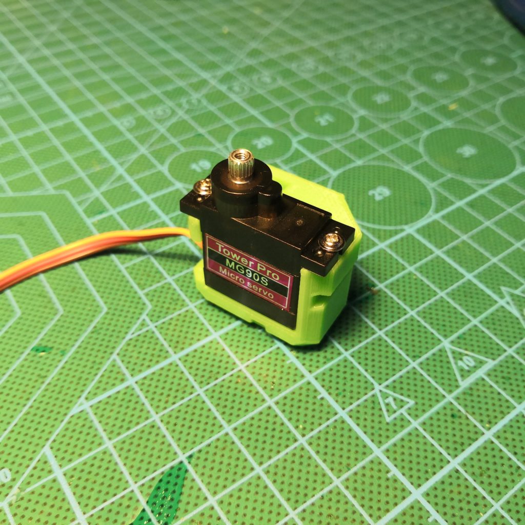
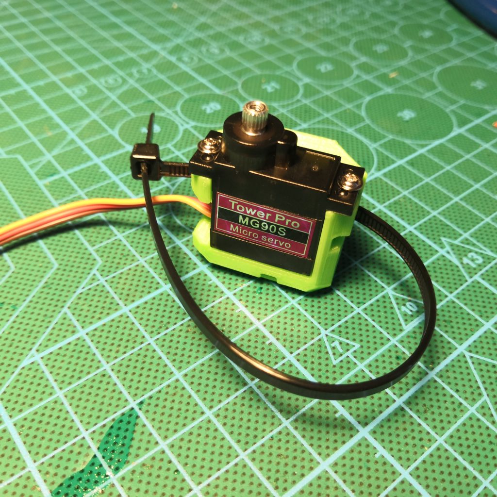
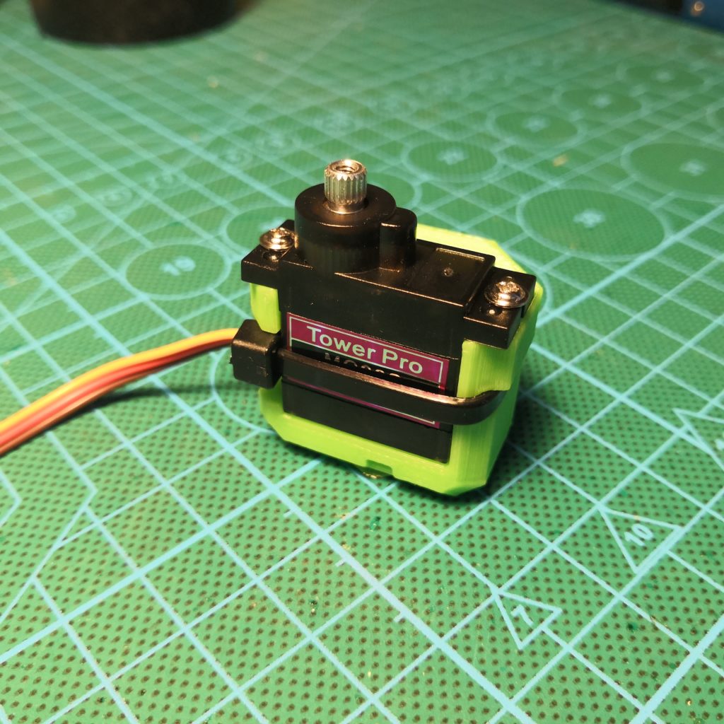
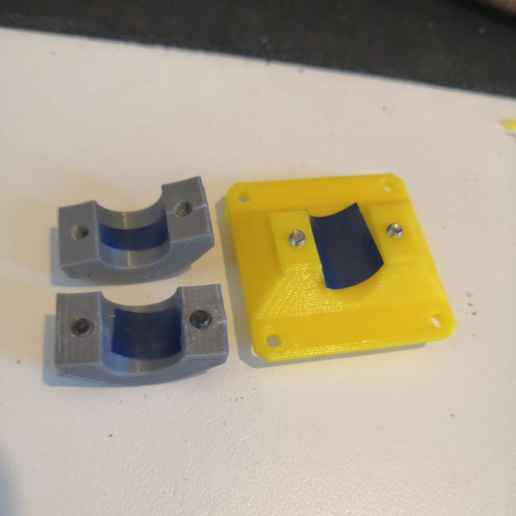
After that you put the servos into their mounts, using screws and a ziptie to prevent it from ever going anywhere. I used rather big ziptie but a smaller one is also fine for sure. Just don’t forget the screws, they are what keeps the servo from sliding in its slot.
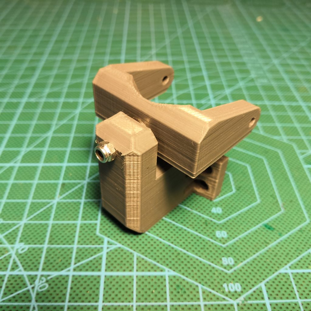
On the both sides of the servo mount there is this little slot whre you slide an M3 nut into. This is where the clamp and screws will screw into.
You of course need to make four of these.
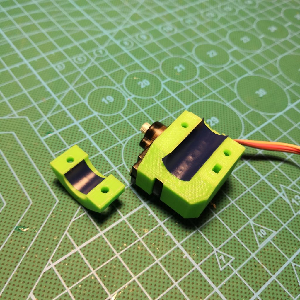
Before going any further, a suggestion: put a small piece of electrical tape, or some other “rubbery” tape, into all the parts that clamp together around the main carbon fiber tube. This makes them grip a lot better to the tube and does a good job in preventing them from spinning around. Plain PLA against carbon fiber tube is a little slippery.
All the clamps are mounted with M3x12mm screws, except for servos which are mounted with 10mm long screws.
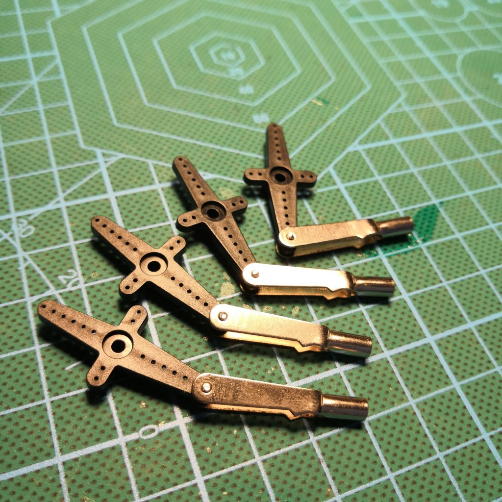

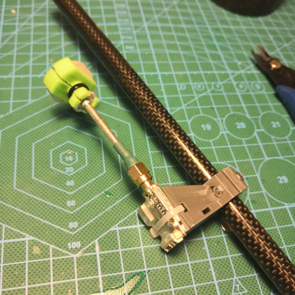
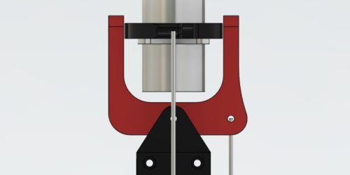
Making of the push rods and servo links. Use the longest servo arms that comes with your MG90S servos, it’s the other half of these shown. Then you need to widen the hole to fit these maybe little too big servo links (left). On the right image is shown how I used M3x50mm screws to make these push rods, first I put the screw trough the cutters and then screwed it into the plastic ball joint. Then cut the other end off at right length and screw your servo link into that. Little tricky but does the job well.

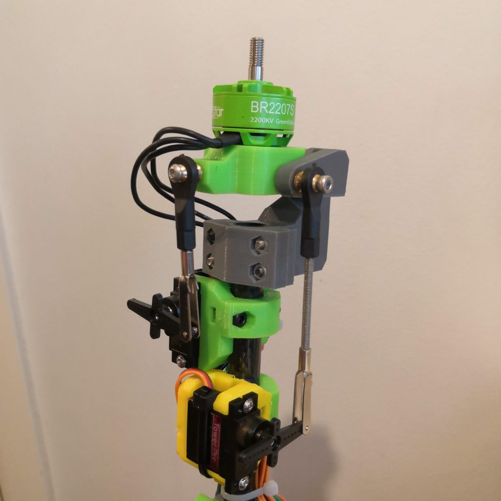
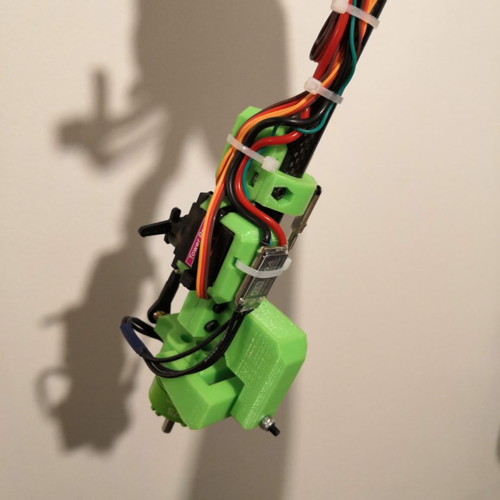
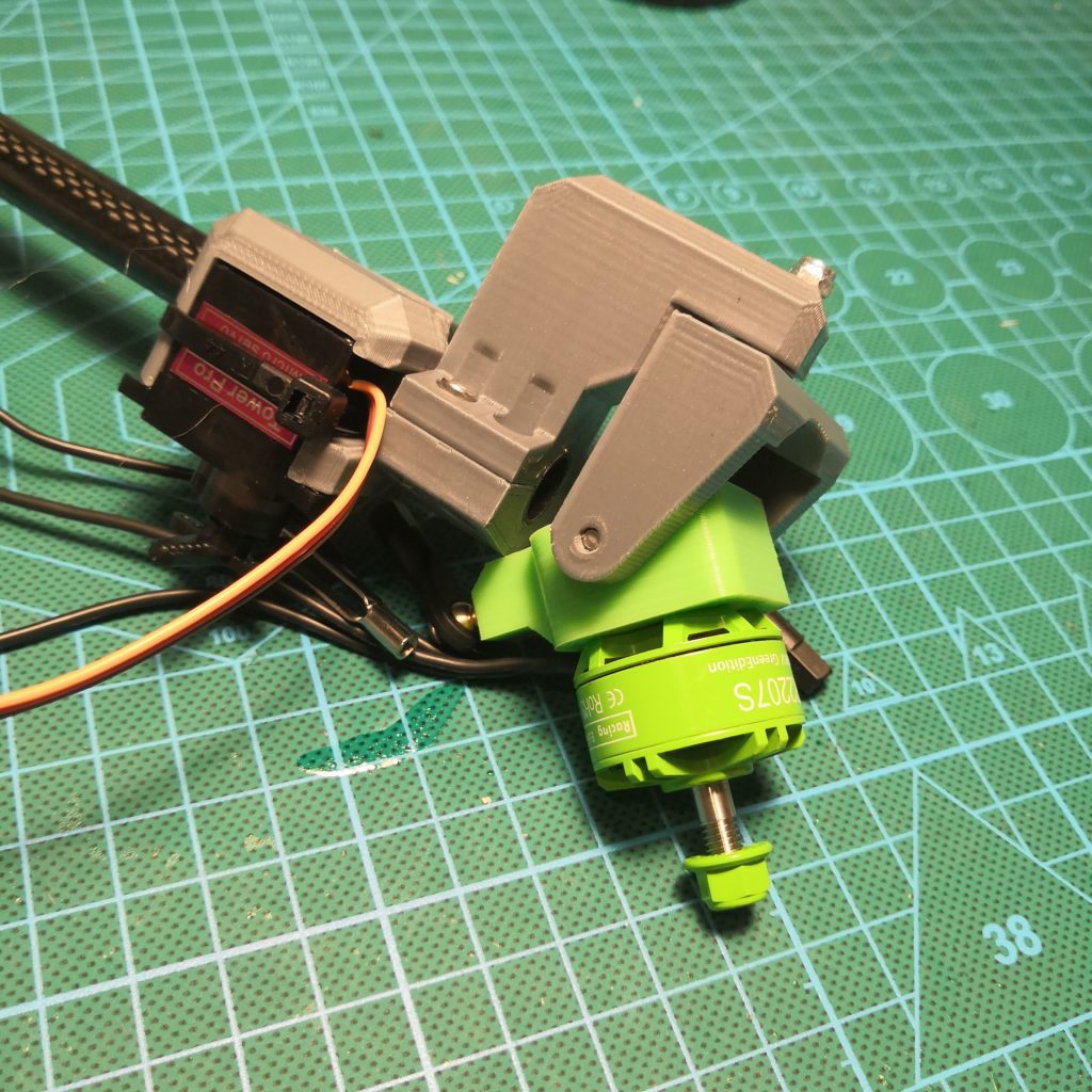

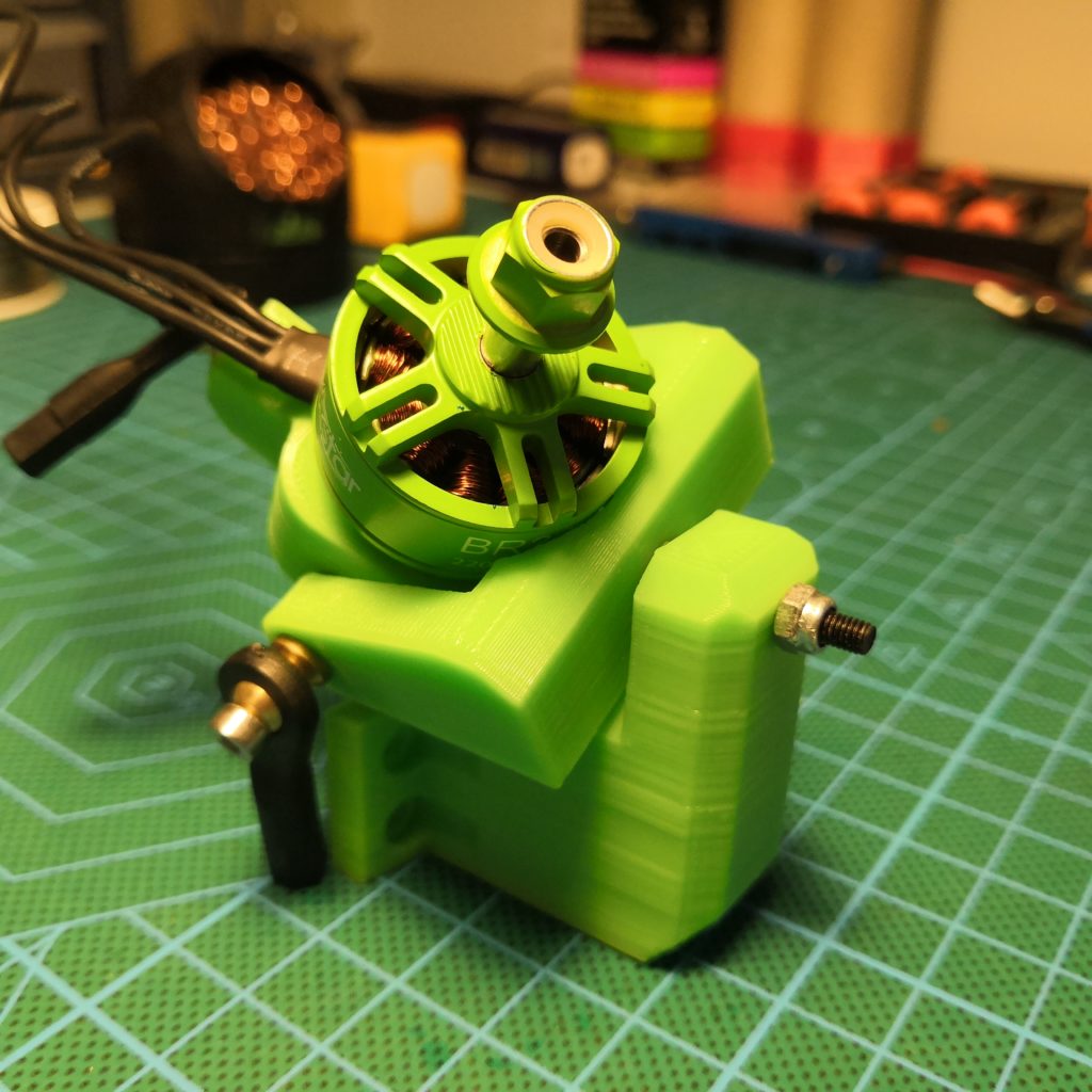
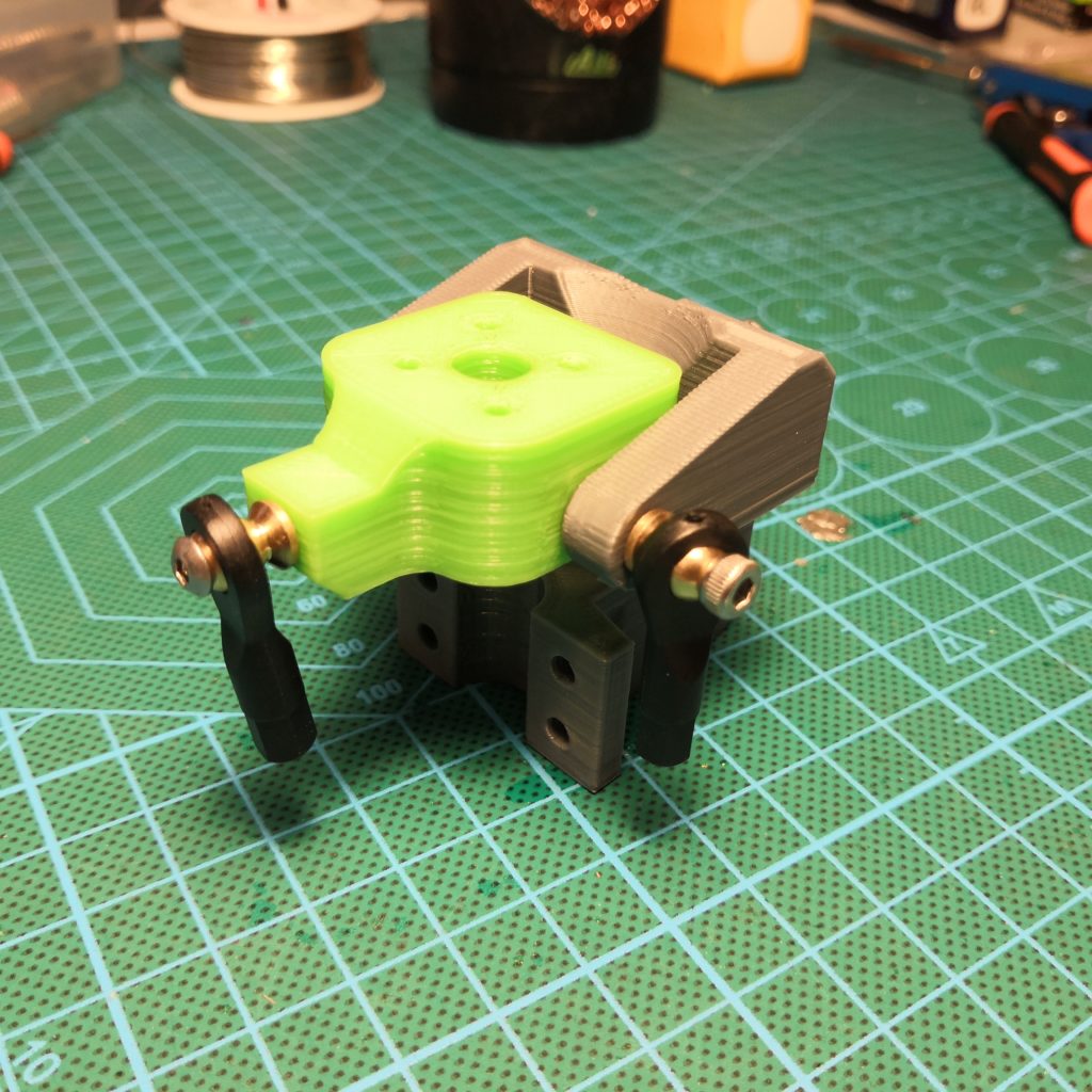
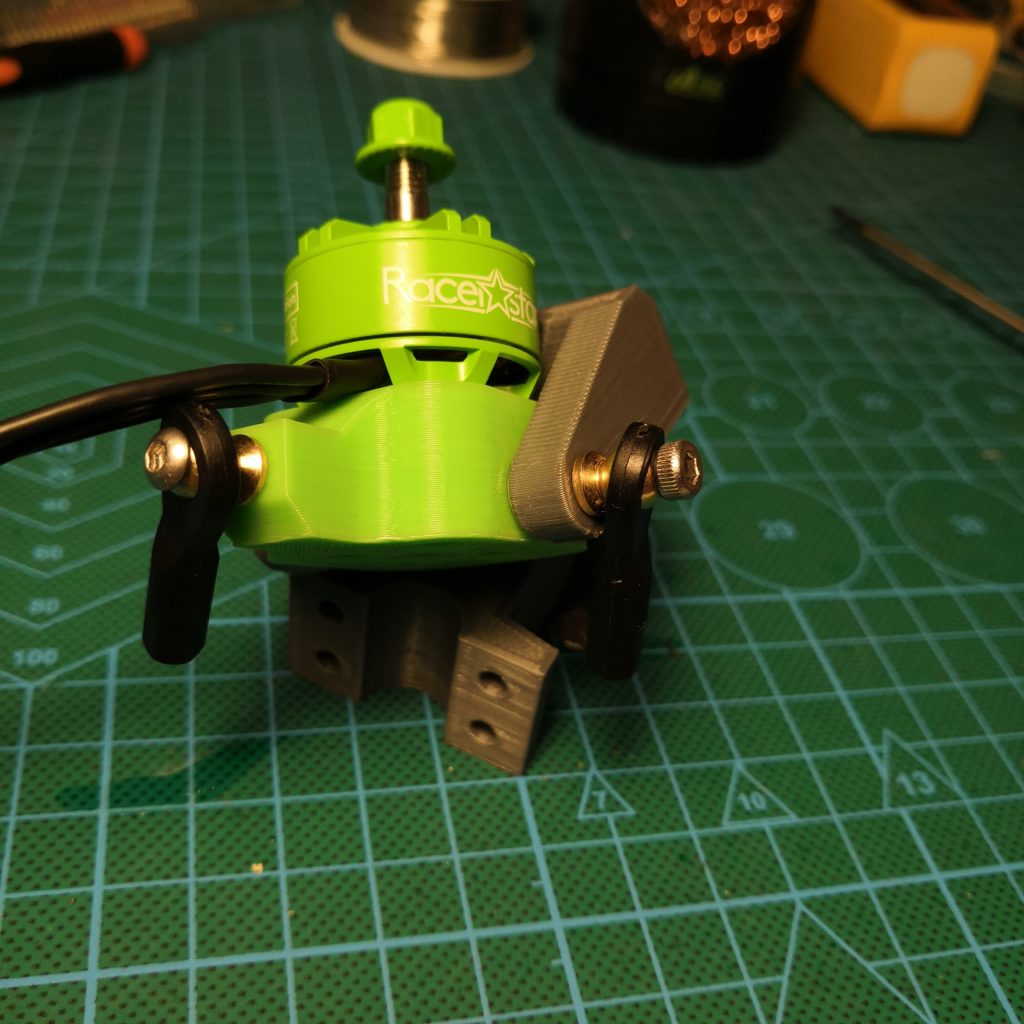
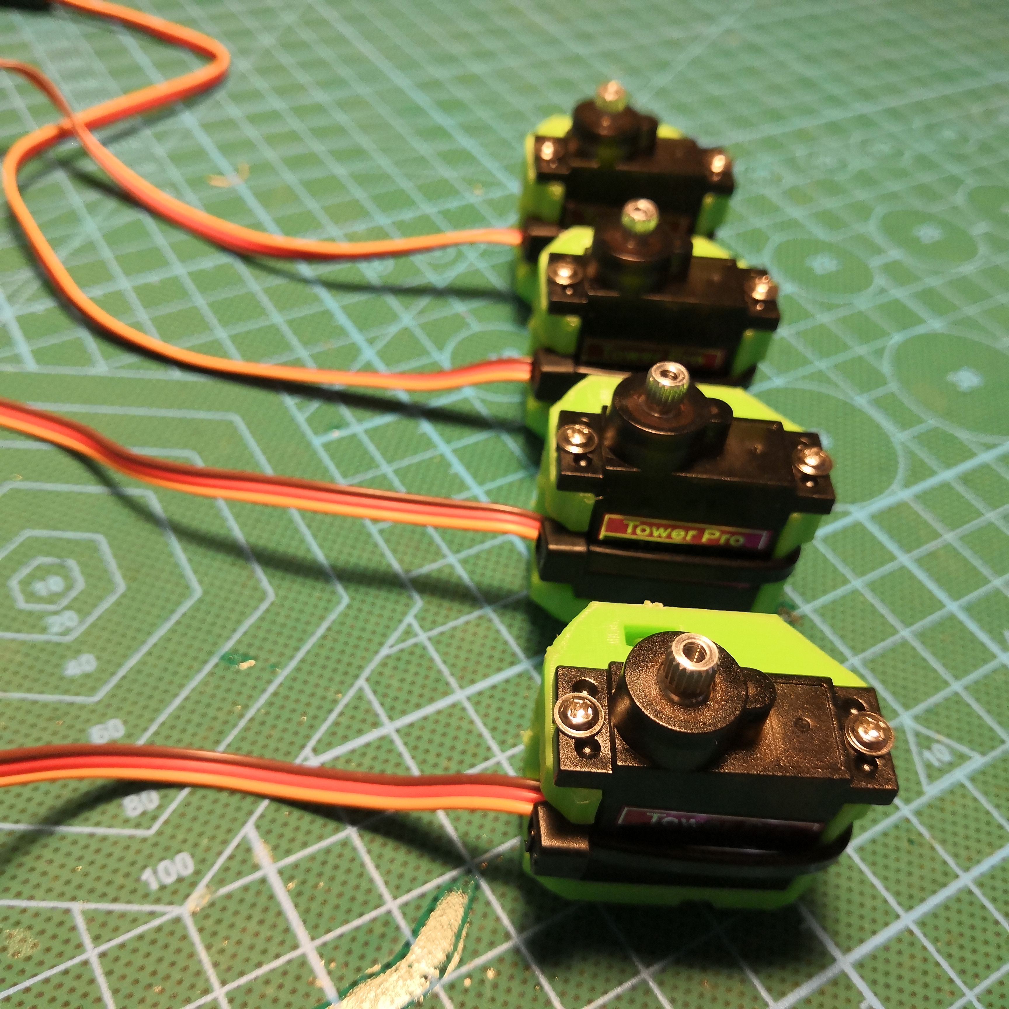
This is how the motor gimbal assemblies should look like. First pic is just showing nuts embedded into the print. Servos are in 90 deg angle and arms in parallel with gimbal joints. You can also see how the ESC is supposed to be mounted on the servo mount too. Wires can be managed with a ziptie on the other servo mount using those same holes.

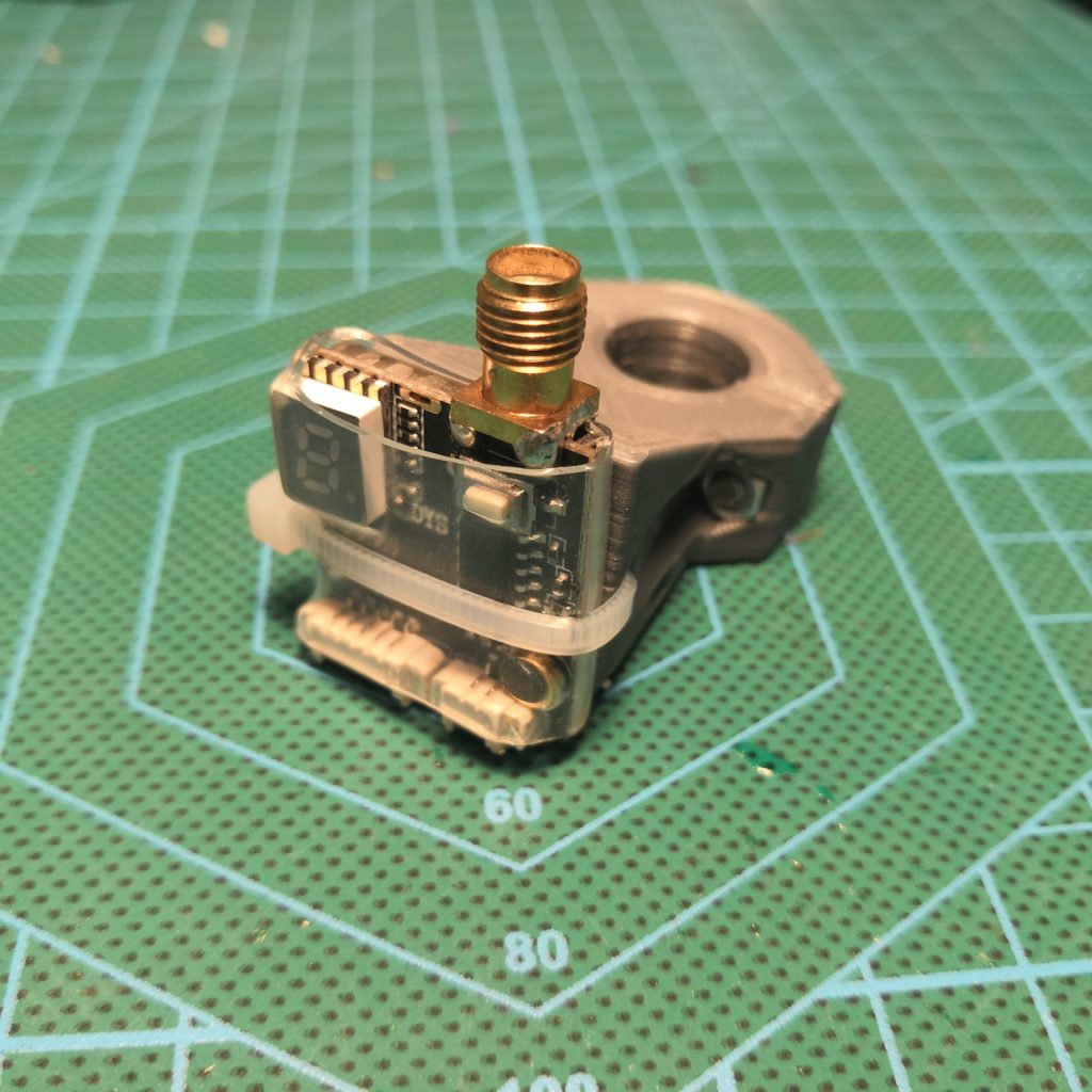
The VTX mount is really simple. The VTX I used is and older DYS Mi200 that still works fine. This mount was made to mount is perfectly but it should just as well work with any other VTX around the same generic size. The second hole for ziptie is to manage wires neatly. I then later stacked also the RC receiver on this same mount. Not sure if theoretically the best way to do it but it works. I put my VTX mount point to the right so that when I fly in line of sight I know that when antenna is on the right, the back is facing me.
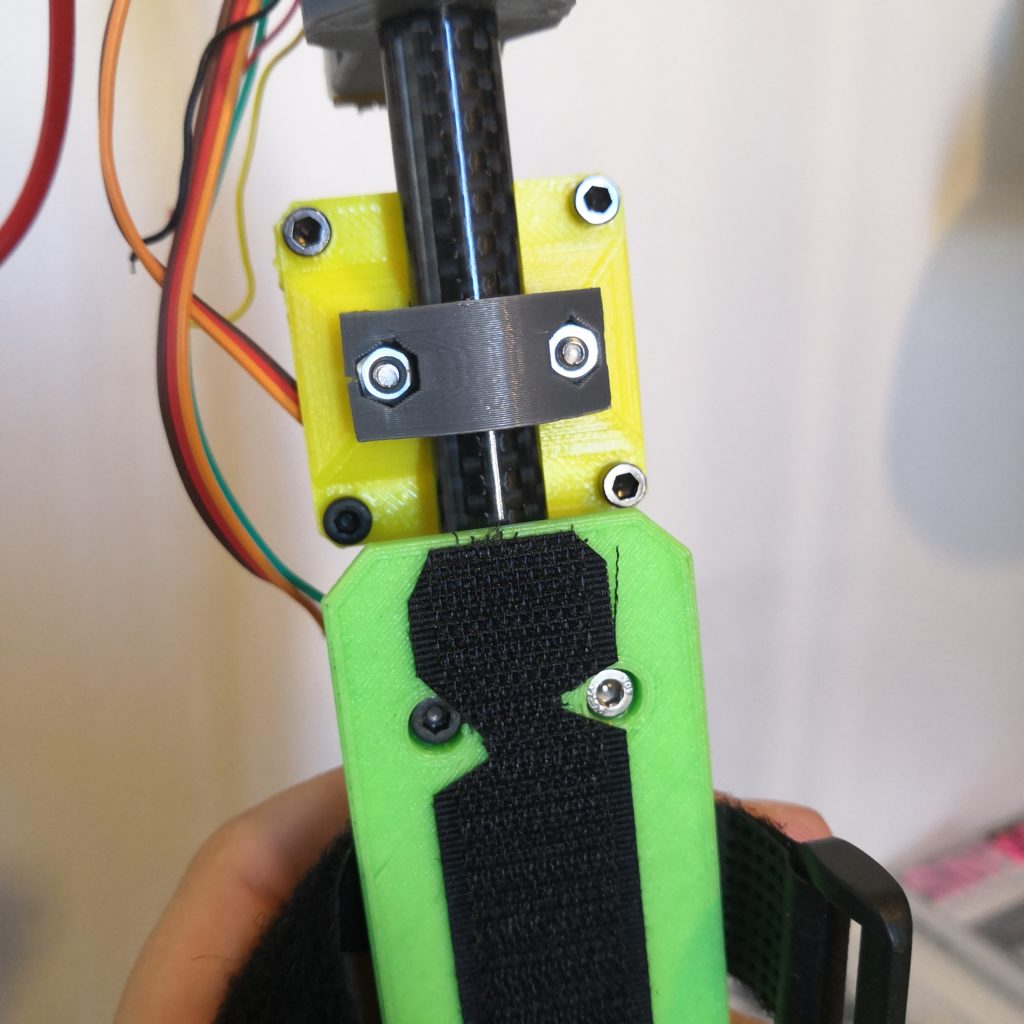

Flight controller and battery mounts are very similar. You want these to be almost in the middle of the tube so that center of gravity is somewhere between FC and battery. Use M3x20mm screws to mount the FC. Don’t forget to use hook & loop or dual lock on the battery mount. The battery strap then goes between the mount and the tube.
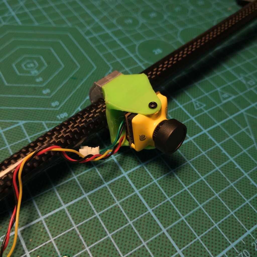
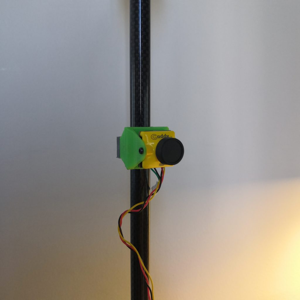
Camera mount is for micro sized cameras and is similar to VTX mount.
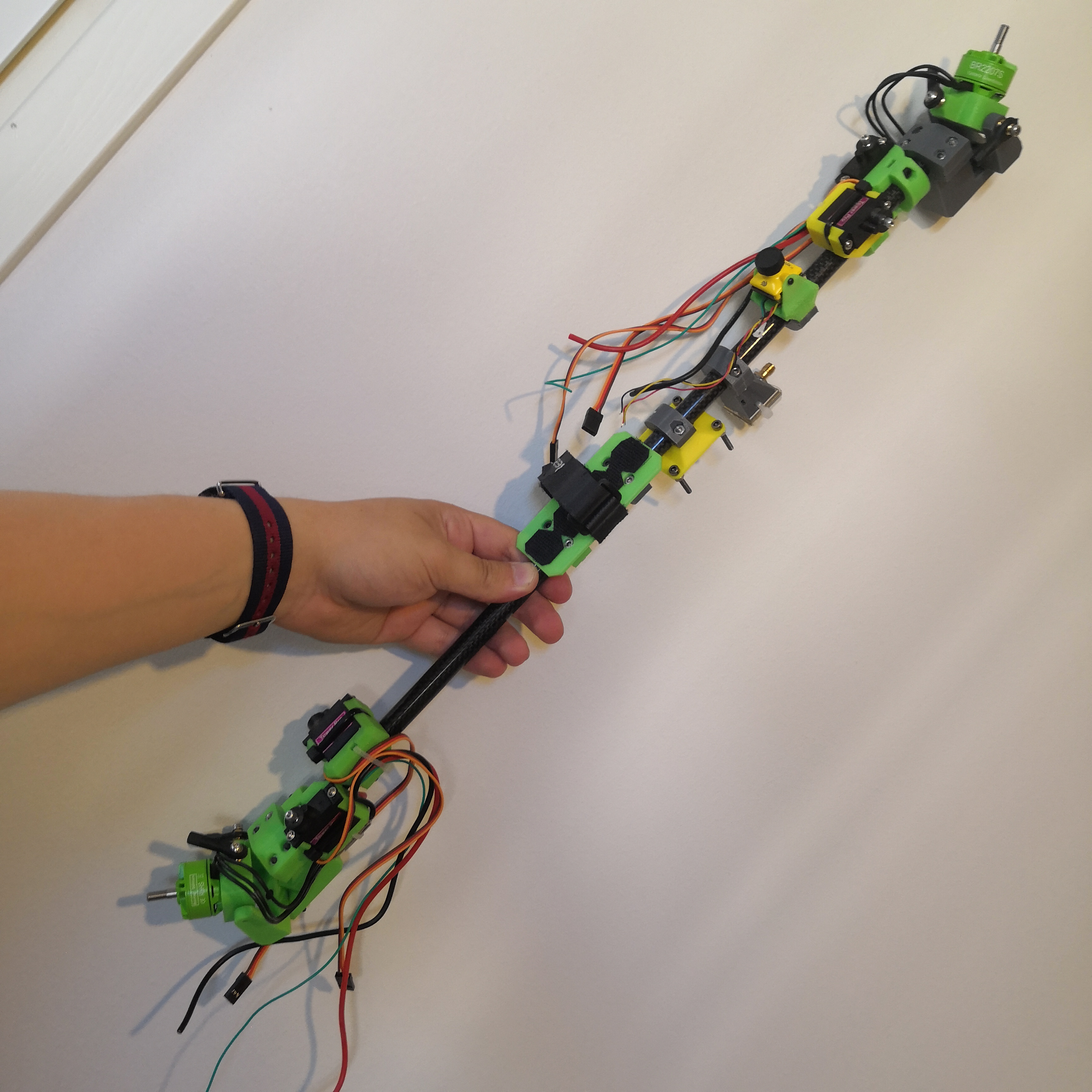
At this point you should have things pretty much assembled around the tube. Here you can also get the idea where to mount everything.
Wiring
Wiring process for this is actually fairly simple. Servos use motor signal pads S1-S4 and motors use pads S7 & S8, at least on this flight controller.

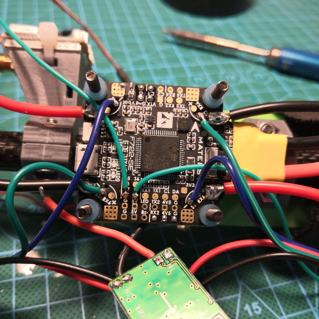
These two photos show pretty well where to connect different things. And even then it doesn’t really matter because you can change everything from the configurator. One thing you must do however is to power all the servos from a BEC, the fc alone likely won’t be able to handle all the current drawn by servos alone.
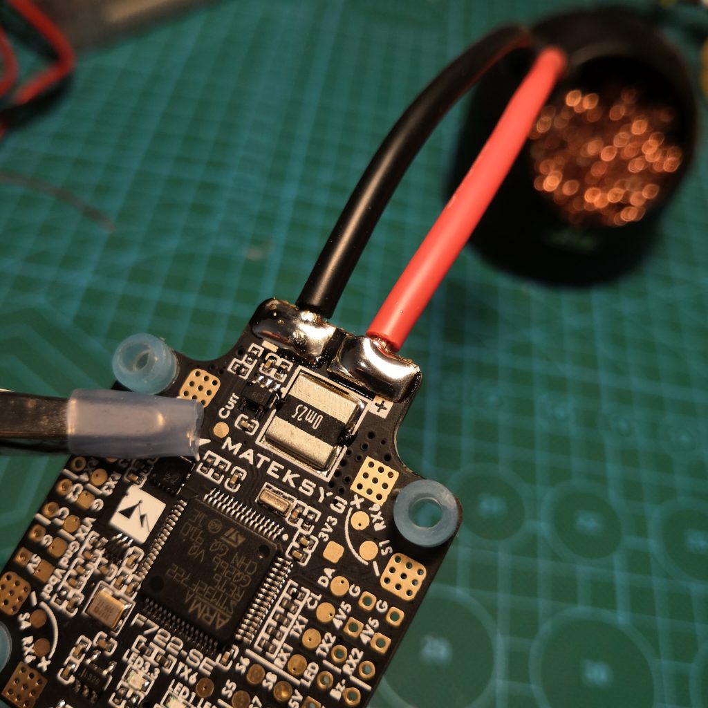
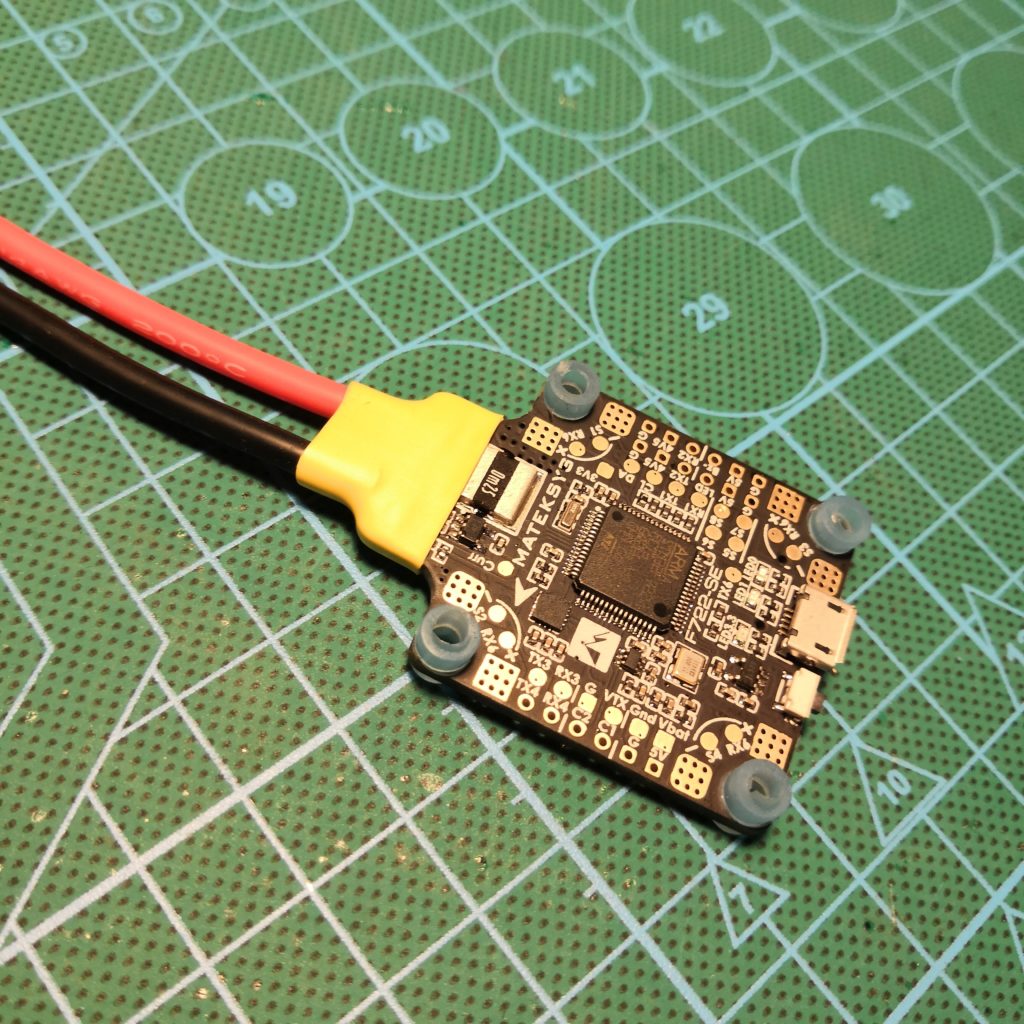
Main power lead can be pretty long, mine is little over 10cm.
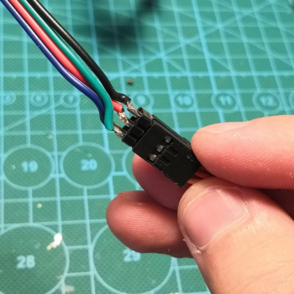
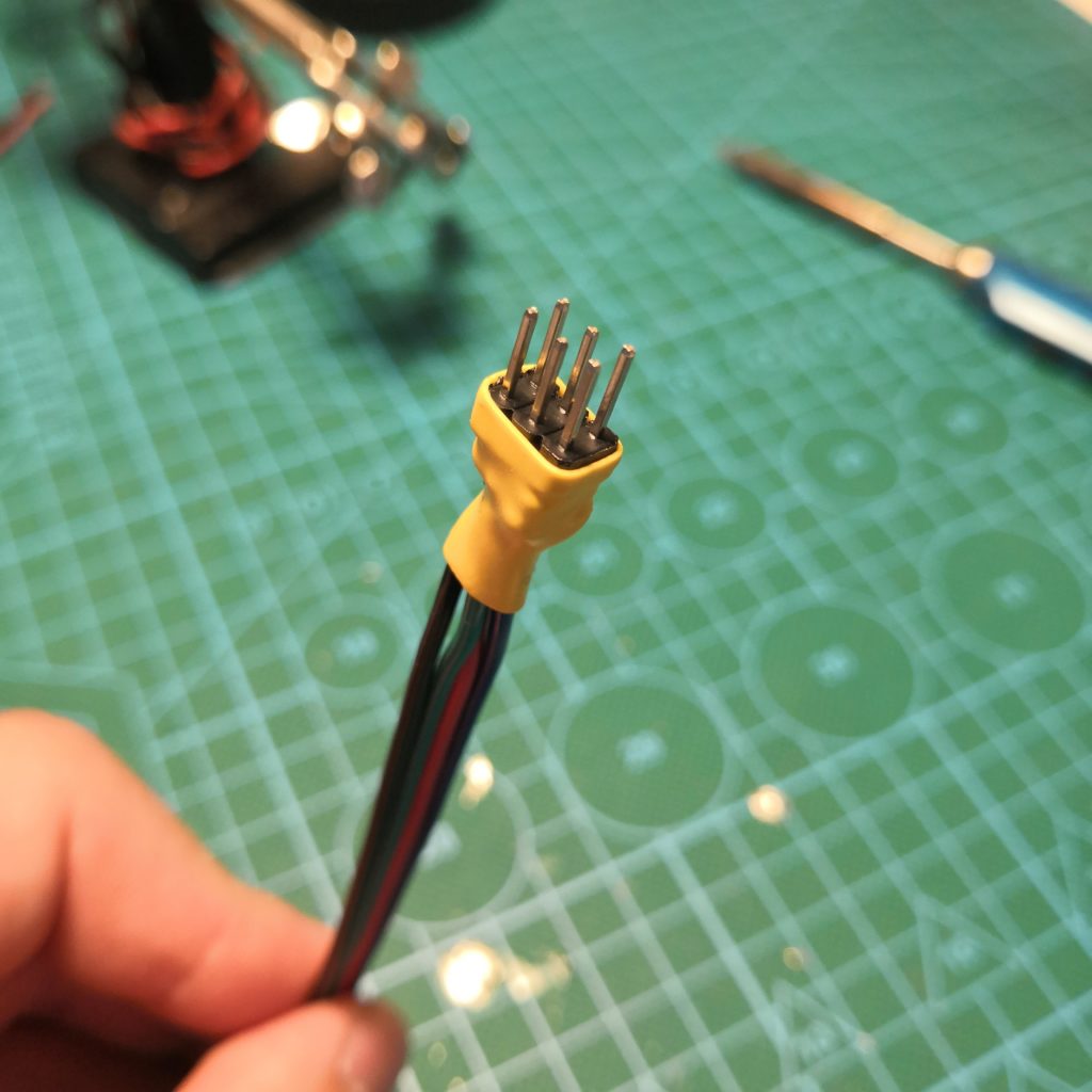
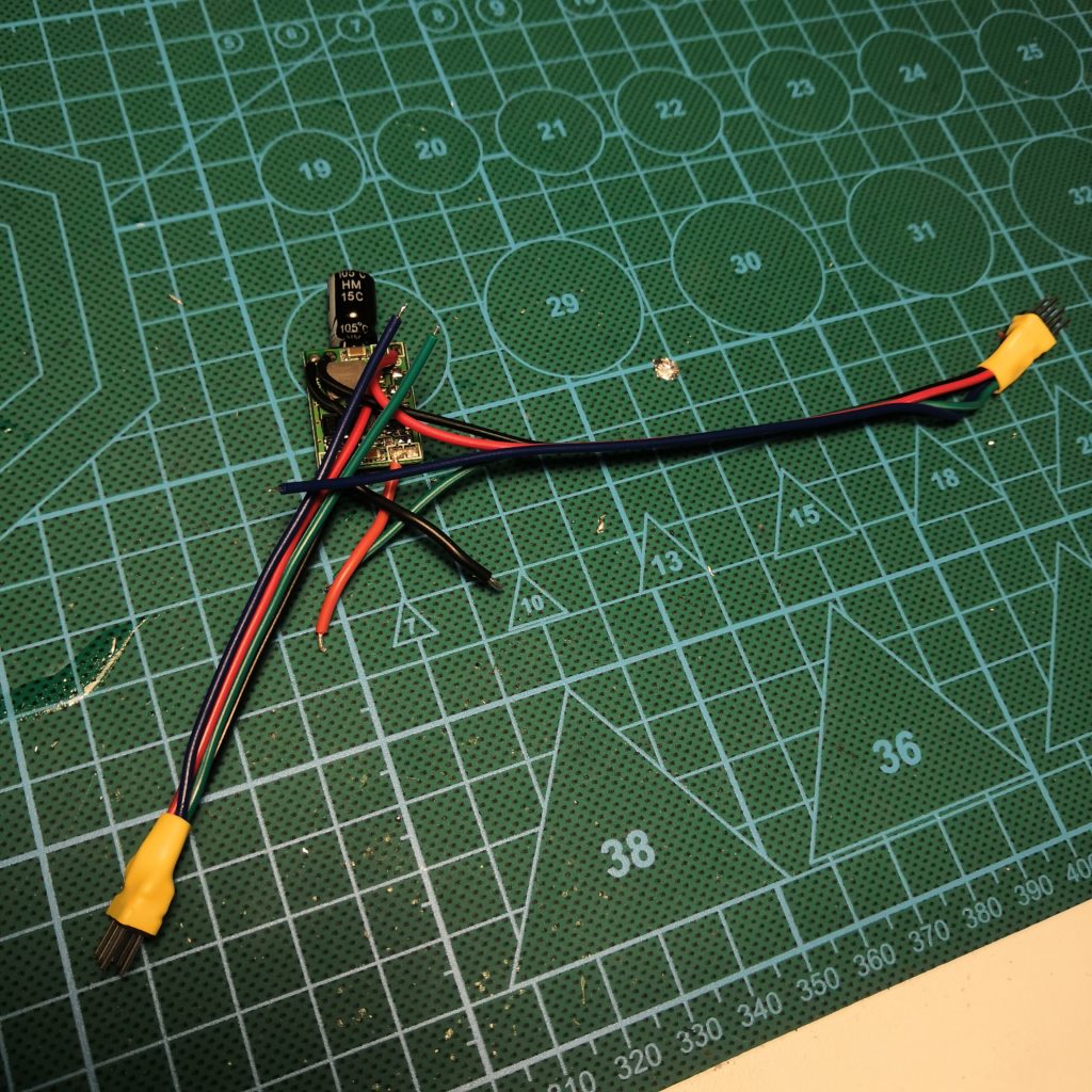
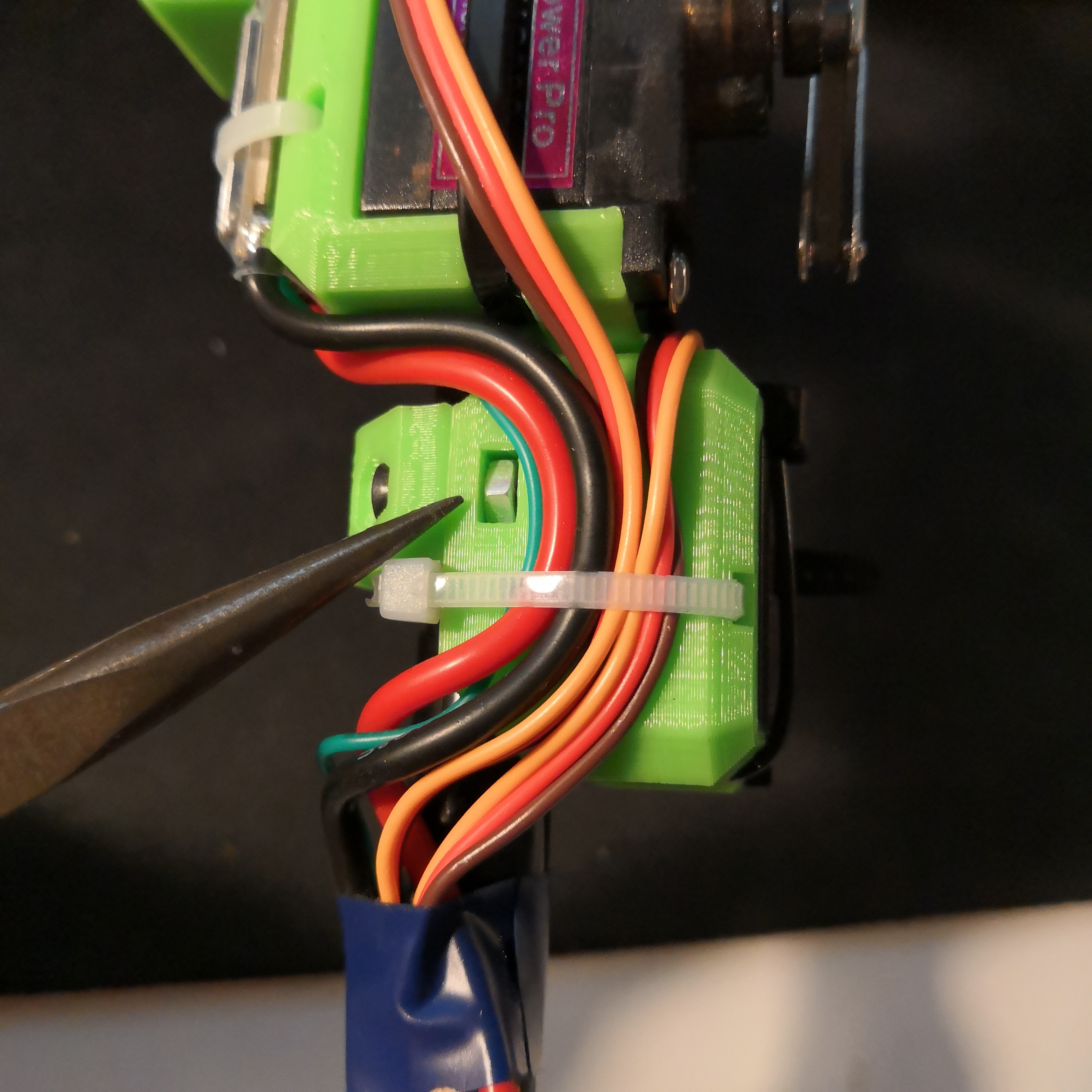
I made these adapters for servos. Power from BEC and signal wires go to the FC. Cleans things and makes possibly needed maintenance easier later on. Also helps during the configuring because you can change the servo pins position super easily.
Rest of the components like receiver, camera and VTX connect just normally, nothing special.
Optional: If you want to, you can add a pretty long LED strip to the back of the thing.
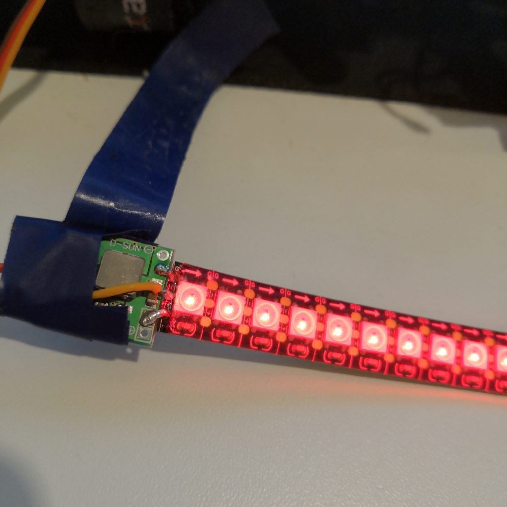
Here I connected a BEC directly to the LED strip because I found that to be the easiest way of doing it. LED strip this long will need a BEC. I set my LED strip to show battery status, makes it easier to fly in a line of sight.
Configuration
If you have been setting it up the same way than I, and with similar enough parts, then you might be able to just use all the same configurations than I have. But most likely you will not be able to do that and you should anyway use these configurations as some sort of baseline for your own configs.

This is the most important one. The Mixer. As you can instantly see, this flying stick thinks it is an airplane. Which it clearly is not but it doesn’t matter in this case. Here you mostly just need to play around with different settings until things work they way they should.
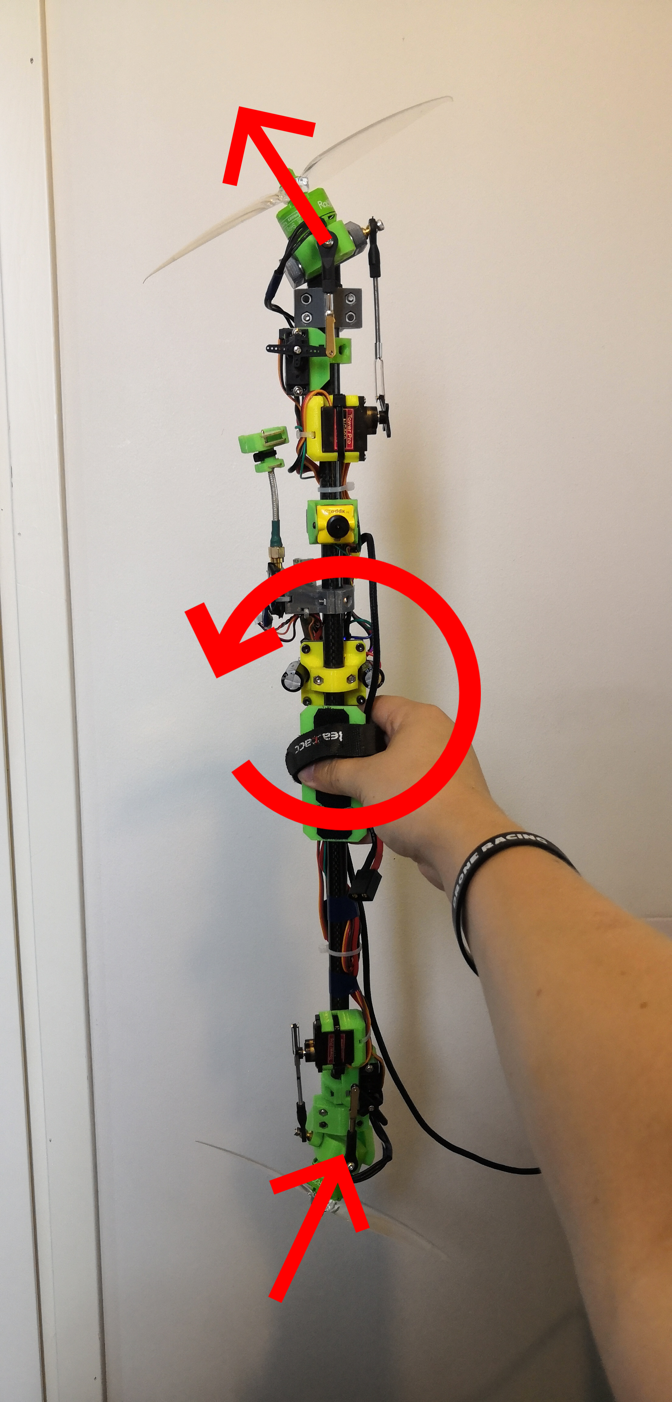
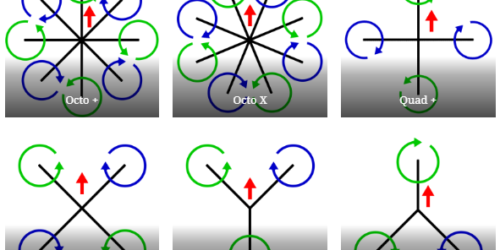
Roll/Pitch: This picture hopefully explains how the motors are supposed to move to make the body rotate in one direction or the other. Same principles apply to each direction.
Yaw: I have top motor rotating cw and bottom motor rotating ccw. You can of course have them another way around. Just make sure your flight controller knows what’s up. As you can see from the mixer tab picture, I have only one of the motors doing yaw action and it is enough. Servos do not participate in yaw movement.

Because this is configured as an airplane it does not use PID control loop, but PIFF. FeedForward must be set to 0! At least on my configuration the thing went crazy if I raised my FF values. P and I terms are tunable but not much. What I have here work for me pretty good.

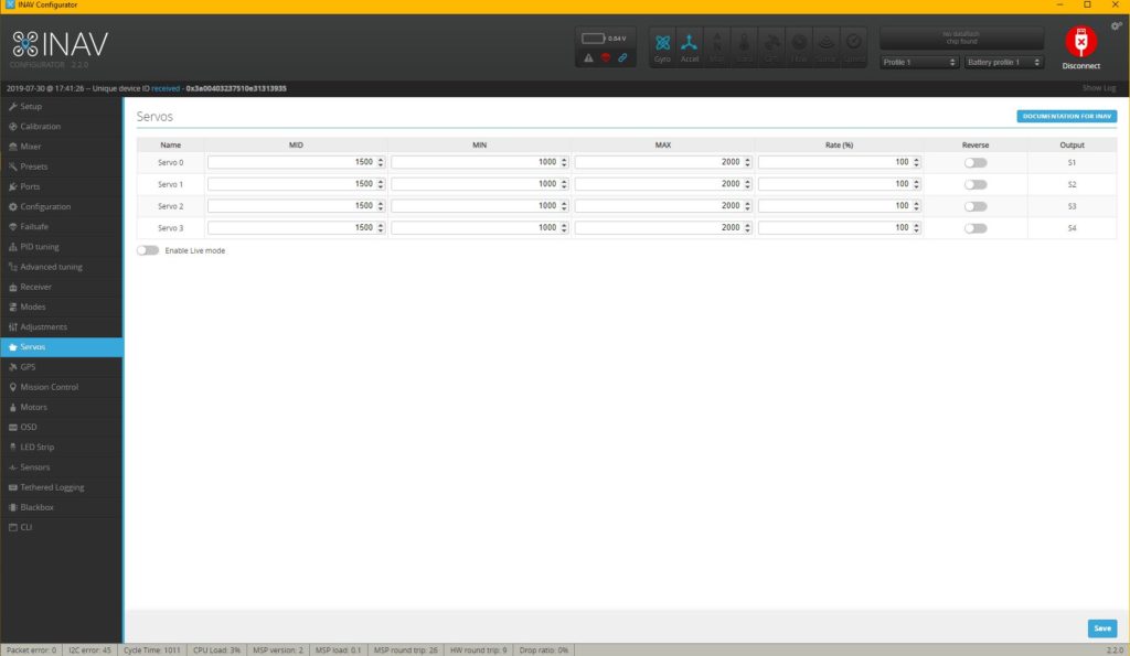
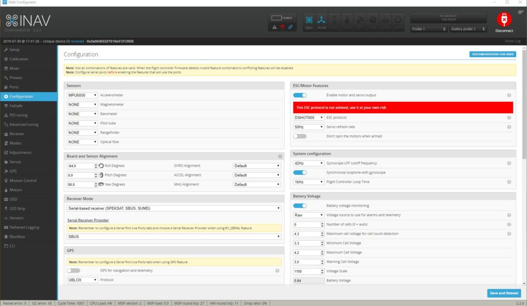
Just some other config screens with not so important things. Servo tab is all on defaults and configuration tab is pretty user dependent. On “Board and Sensor Alignment” I have Roll on -84 degrees to tune in the FC position. You might have to tune these values on your build too, depending on how exactly perfect build you make.
Resources:
CLI Dump
My settings, be careful if copy pasting these into your build!
3D-printed parts
All the 3D-printed parts can be found from Thingiverse.
Parts list
Full parts list for what I used can be found from Rotorbuilds.
If you have any questions on you think this page needs to improve some part of it, just leave a comment below.
Sogood
hello anders,
do you have the flying test details. can your flying stick be equipped with thermal camera & 360 anti collision devices and autonomous flying?
Hi!
I don’t have any specific details about any flying test but it does fly really well.
I’m sure you can equip one of these with whatever cameras and sensors you want, you just have to make it happen 😉
I tried this setup with a different frame, however I noticed in angle mode, while throttling up the pitch servo starts to give output without any input given on pitch channel. What might be going wrong here? Also kindly let me know if we can have an in depth discussion about this project for a new model development.