
LEDs on FPV goggles, Ver 2.
In June 2018 I made a first version of these LEDs on FPV goggles. They were cool! They had 12 different animations to run on them and they definitely got some attention everywhere where I was flying. But now it is 2019 and time for something new! During the last race of 2018, me and a flying buddy of mine were talking about these and we thought that they should be responsive to my transmitter so that they would actually have some function. That’s what I have done now.
This is my instagram post from June 2018.
Making of the new version
So, the thing uses arduino nano to control LEDs and take in receiver signal in SBUS from. This creates instantly one problem, SBUS needs to be read with serial port, and arduino nano only has one serial port which it shares with USB, so I can’t use USB and SBUS signals both at the same time. That’s a problem when you need to develop something and see if it works. How I solved this is that I developed the code using arduino mega 2560, because it has more serial ports, and then ported the code to run on arduino nano once I was done with it. Or this was my plan, later on it turned out the sketch I had done on mega was too big to fit on a nanos smaller program space so I had to re-write portions of it drop one library out.
Because most of the changes from previous version would be done in code, the bill of materials needed for this upgrade was quite short. Only receiver and some basic electronic components for SBUS inverting circuit were needed. List below.
- Redcon FT4X 2.4G Mini SBUS Receiver
- BC547B general purpose NPN-transistor
- ~5 kOhm resistor (I used 4.7) and 10 kOhm resistor
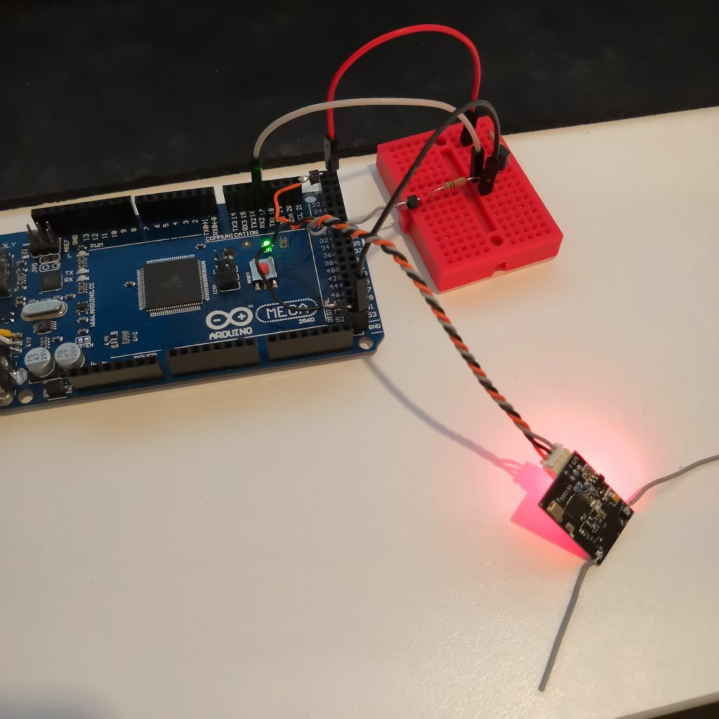
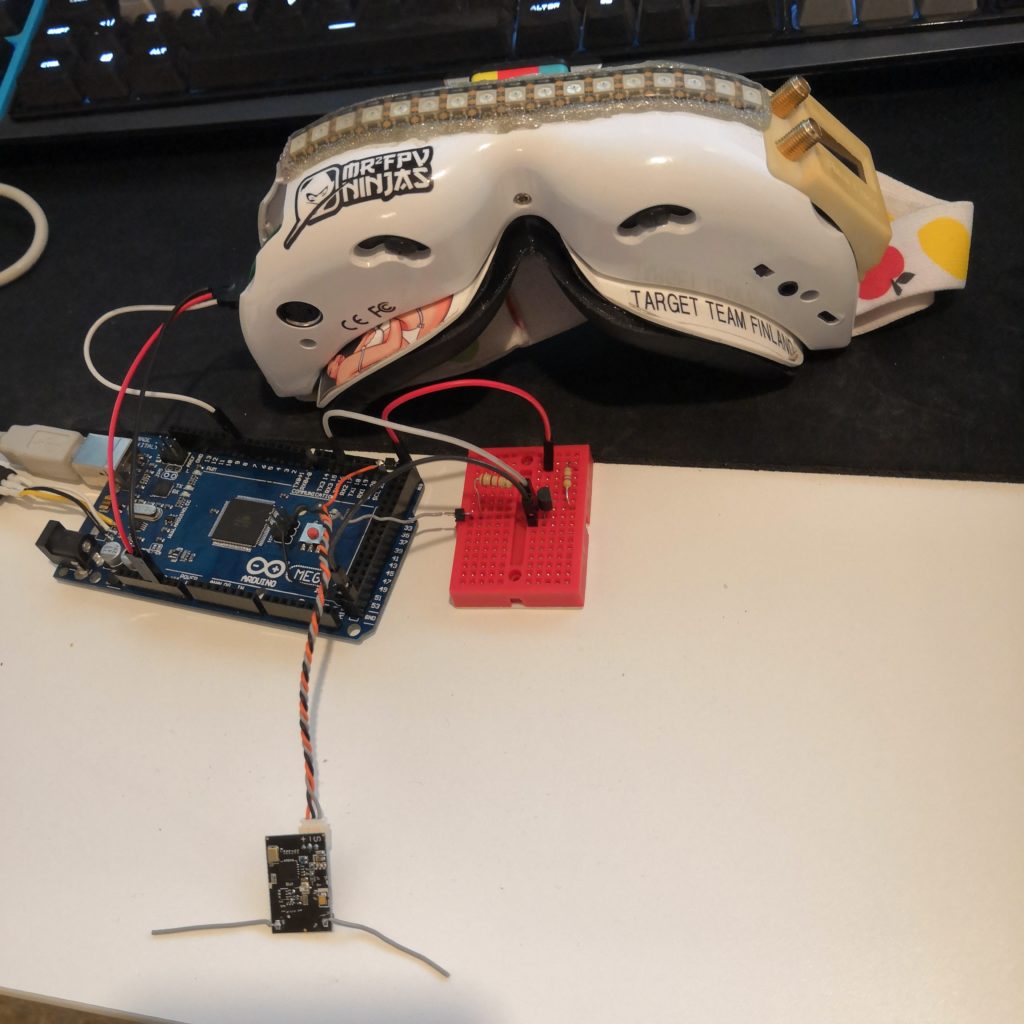
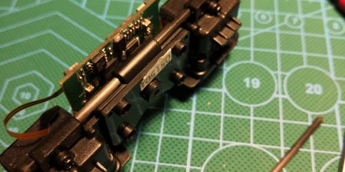
Here’s my simple development environment for this. SBUS signal being fed to arduino via the inverting circuit on breadboard. Later that circuit was soldered to very small form factor in order to fit inside the case on goggles.
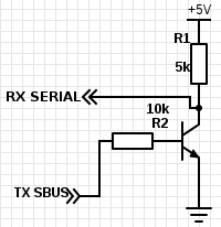
Here’s a diagram for the inverting circuit. It’s from zendes arduino library for Futaba SBUS. This is the library I used for this project and even if it might not be that well documented it worked out pretty well. It does have some limitation when running on a nano or similar board but I kept that in mind while making the code so it was not a problem.
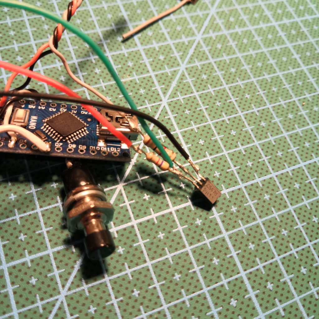

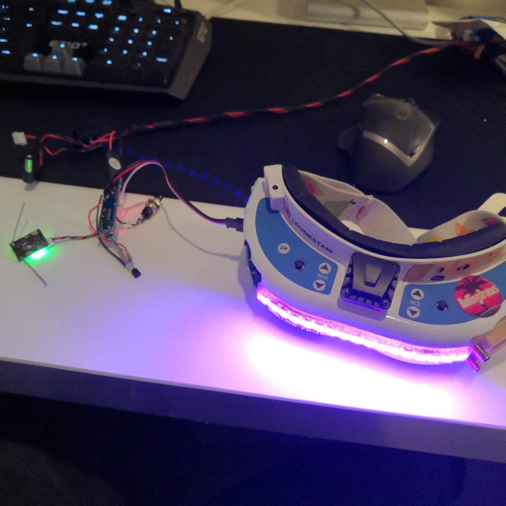
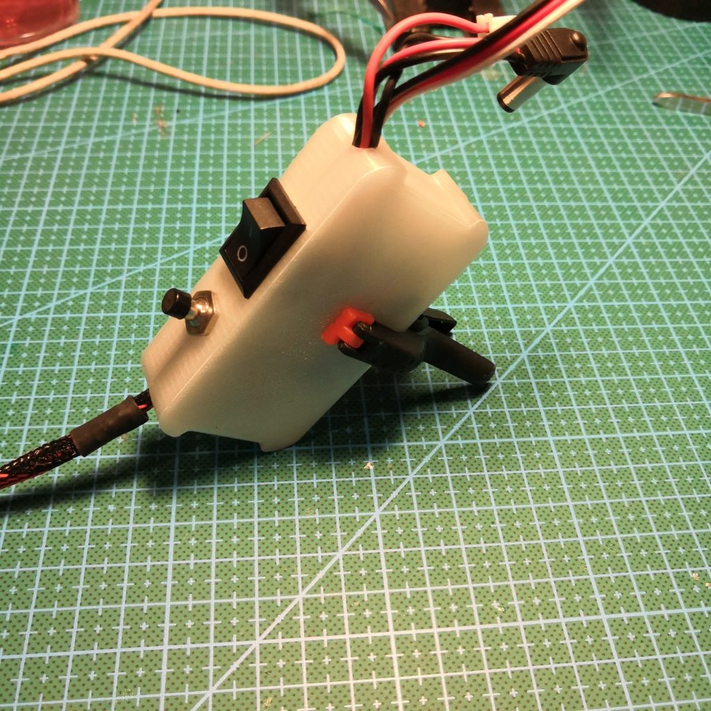
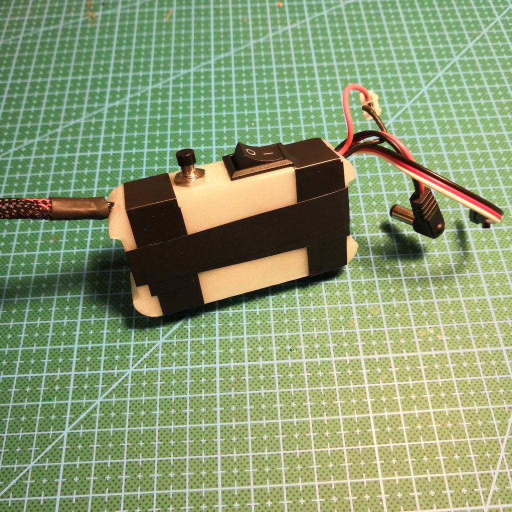

I don’t think there’s much to tell about making of the code. Took me three evenings to get familiar with arduino sbus combo and to make it work. First I used FastLED and WS2818FX libraries to light up LEDs but as mentioned earlier I ran out of program space on nano so I dropped the WS2812FX library out and did everything with FastLED library. That was not really much of a problem, just something that took me like an hour to write some of the code again. As you can see from the pictures, as a case I used 3D-printed “transparent” case wrapped shut with electrical tape. I know this might not be the best or the prettiest solution out there but I did this for four different reasons:
- Originally I had plans to put LEDs also inside the case but eventually decided not to for different reasons.
- I can see the status lights of the arduino and receiver through the case, this should help is something decides not to work.
- I think this look works well with “scratch build” look of my goggles too.
- Electrical tape has to be the easiest and most reliable way if and when I need to take this apart again for some reason.
How it works
Only user inputs for this are still just a power switch and one button to change between different modes. Of course this could easily have more inputs too but I don’t think it really needs to.
Here’s how it works:
- When you turn the power on, it checks if the mode button is pressed
- IF NOT, then the arduino enters “sbus mode” which takes inputs from receiver and displays leds accordingly.
- IF IS, then the arduino enters “passive mode” where is runs different animations on the led strip. I added this so that I can have the leds to display something even if I’m not flying, or have different transmitter etc.
Video
A short demo of this in action showing all three different modes.
Files
This post is not really a tutorial but I’ll leave files here if someone is interested to build one of these or something similar and use this as reference.
- 3D-printed case for electronics
- ledsync.ino, code to run on arduino
- Betaflight leds CLI dump

How much power does this suck? Without the arduino or receiver, how big of a 5 volt regulator did you put in?
I have the arduino, receiver and led strip all running from one of these UBECs.
what kind of switch did you used to change the mode? and is it maybe possible to post a image how to wire all the cables on the arduino?
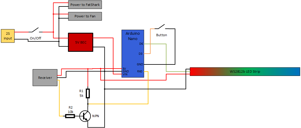
I used just some very basic momentary button. I can make complete wiring diagram too. Check back in few days 🙂
Hi! Sorry it took me a little longer but now this post includes complete wiring diagram.
Hi, thank you a lot 🙂
Hi, I finished my build now. But there are some problems with it. Maybe you have an idea?
I use a Frsky XSR Receiver. This will not work with the normal SBUS library for Arduino, right? And I can’t change the different modes. If I turn on my Arduino without pressing the button I am in the SBUS-Mode, so I can swith the three different modes (like your video). In mode 1 and 3 the LEDs are static yellow (because I don’t get the signal from my RX). But if I turn on my Arduino while pressing the button, it should enter the “passiv”-Mode. But then nothing happanes. There should be a cycle of all colours on the LEDs? And even I’m in the “passiv”-Mode, I can change throug the three SBUS-Modes?
I will try to get it work correctly, but maybe you have an idea?
best regards, Pascal
Now it works. Only thing I changed, was the two resistors for the inverter. R1 is now 10k an R2 5k.
Great to hear you got this figured out! Let me see your creation in action when it’s done! 🙂